

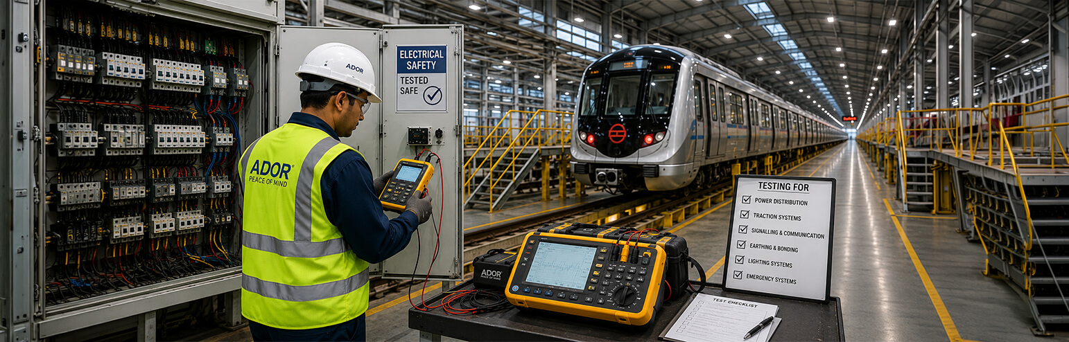
Electrical Testing Requirements for Metro Rail Infrastructure Projects
Metro rail networks depend on a continuous and controlled supply of electricity for train movement, stations, depots, signalling, ventilation, lighting and other essential systems. A fault in a circuit breaker, traction motor, switchgear panel or insulation system can interrupt operations and create serious safety risks.
For this reason, electrical testing requirements for metro rail infrastructure projects must be defined during the design stage and followed throughout manufacturing, installation, commissioning and maintenance.
The exact testing programme will depend on the traction system, equipment voltage, approved project specifications and applicable standards. However, every metro rail project must verify electrical safety, equipment performance, protection functions and operational reliability.
Why Metro Rail Electrical Testing Requires a System-Level Approach
Metro rail infrastructure is not a single electrical installation. It includes receiving substations, traction substations, auxiliary power supplies, switchgear, circuit breakers, cables, protection systems, control panels and traction motors.
Effective metro rail electrical testing should therefore include:
- Factory acceptance testing before equipment dispatch
- Site acceptance testing after installation
- Individual equipment testing
- Protection and interlock verification
- Integrated system commissioning
- Periodic and condition-based maintenance testing
RDSO’s safety-clearance procedure for metro systems requires project authorities to submit test plans and results, details of electrical protection systems, standards followed and evidence supporting the reliability of major assemblies and sub-assemblies. This makes accurate testing and traceable documentation essential.
1. High-Voltage and Insulation Testing
Electrical equipment used in metro rail projects must withstand its specified operating voltage without insulation breakdown.
High voltage testing for metro rail may be required for circuit breakers, switchgear panels, traction motors, cables and other electrical assemblies. Depending on the equipment and approved test procedure, the tests may include:
- AC voltage-withstand testing
- Insulation-resistance measurement
- Dielectric-strength verification
- Leakage-current monitoring
- Insulation condition assessment
IEC 60060-1:2025 covers general requirements for dielectric testing using alternating, direct, impulse and combined voltages for equipment above its specified voltage thresholds. The precise voltage level, duration and acceptance criteria must come from the project specification and applicable equipment standard.
Crest Test Systems’ CT-HVT Series provides automated AC high-voltage testing with capacities of up to 100 kV RMS at 50 Hz. It can support controlled factory testing of suitable electrical equipment within the system’s rated capability.
2. Circuit Breaker and Switchgear Testing
Circuit breakers protect traction and auxiliary power systems by opening or closing the circuit under normal and fault conditions. Testing must confirm both their electrical integrity and mechanical performance.
Important checks include:
- Main and auxiliary contact timing
- Opening and closing time
- Contact travel and operating speed
- Trip-and-close coil current
- Spring-charging motor current
- Static and dynamic contact resistance
- Operation at minimum, rated and maximum control voltage
- Mechanical endurance
IEC 62271-1 provides common requirements for high-voltage AC switchgear above 1 kV, while IEC 62271-100 applies specifically to AC circuit breakers in this voltage range. The applicable edition and project-specific limits should be confirmed before testing begins.
Crest’s AutoScan Circuit Breaker Test System measures contact timing, travel, speed, coil current and motor current. With suitable accessories, it can also perform static and dynamic contact-resistance measurements. Its modular design allows additional tests to be incorporated when project requirements change.
For repeated operational testing, Crest’s Circuit Breaker Endurance Test System can operate breakers at rated, minimum and maximum voltage levels while controlling the required number of test cycles.
3. Contact Resistance Testing
Poor contacts, loose joints and deteriorated busbar connections can result in local heating, voltage drops and energy loss.
Contact-resistance testing is therefore important for:
- Circuit breakers
- Isolators and disconnectors
- Busbars
- Electrical joints
- Power connections
Crest’s MVT Contact Resistance Meter uses Kelvin’s four-wire method and supplies continuous DC current of up to 200 A. It measures resistance in the micro-ohm range, making it suitable for identifying high-resistance connections in critical current paths.
Test results should be compared with approved limits, previous readings, phase-to-phase variations and the equipment’s maintenance history.
4. Panel, Protection and Interlock Testing
Metro rail electrical panels must be tested as complete assemblies rather than as collections of separate components.
Panel testing may include:
- Primary and secondary current injection
- AC and DC control-supply verification
- Continuity testing
- Coil operation
- Meter and indication checks
- Trip-circuit verification
- Local and remote operation
- Electrical and mechanical interlocks
Protection relays, circuit breakers and control logic should also be tested together. The complete sequence, from fault detection and trip command to breaker operation, alarm generation and control-room indication, must function correctly.
Crest’s Panel Test System combines primary and secondary current injection, multiple AC and DC power supplies, continuity testing, voltage measurement and contact-resistance measurement. Its Windows-based software can help OEMs standardise important parts of switchgear panel testing before dispatch.
5. Traction Motor Testing
Traction motors directly affect train acceleration, efficiency, speed and operational reliability. Their performance must be confirmed under defined electrical and mechanical conditions.
The IEC 60349 series covers rotating electrical machines used in electrically propelled rail vehicles. IEC 60349-1 applies to certain conventional traction machines, while IEC 60349-2 applies to converter-fed AC traction motors.
A traction motor testing programme may include:
- No-load and full-load tests
- Voltage and current measurement
- Power and power-factor measurement
- Speed and torque verification
- Temperature-rise assessment
- Direction-of-rotation checks
- Insulation and voltage-withstand tests
- Efficiency and performance evaluation
Crest’s Motor Type Test System performs full-load assessments on three-phase AC traction motors. Its Motor Routine Test System supports no-load testing of AC and DC motors with configurable sequences, pass-or-fail limits and report generation.
For maintenance depots, Crest’s Light Load Test System measures parameters such as voltage, current, power, frequency, RPM and temperature during motor maintenance and overhaul.
6. Earthing, Bonding, Cable and Continuity Testing
Electrical testing for railway infrastructure must also verify the electrical paths that protect passengers, maintenance personnel and equipment.
Site testing should cover:
- Earthing-system resistance
- Equipment bonding
- Cable insulation resistance
- Conductor continuity
- Phase identification
- Return-current paths
- Connections between electrical equipment and the earthing network
For overhead-electrification and third-rail systems, bonding and return-current arrangements must be coordinated with track circuits, signalling systems and stray-current requirements.
The approved project design and testing method statement should define the instruments, test levels and acceptance limits.
7. Integrated Commissioning and Documentation
Individual equipment may pass factory testing but still fail after installation because of incorrect wiring, unsuitable settings, communication problems or interlock errors.
Integrated commissioning should verify that substations, panels, breakers, protection systems and supervisory controls operate together as intended.
Reliable electrical testing systems should provide:
- Repeatable testing procedures
- Calibrated measurements
- Automatic data capture
- Defined pass-or-fail limits
- Product and asset identification
- Secure test reports
- Easy access to historical results
Crest’s OEM circuit-breaker testing solutions use configurable software and can generate secure test reports in formats based on user requirements. This supports traceability across manufacturing, inspection and commissioning stages.
Choosing Metro Rail Testing Equipment
When selecting metro rail testing equipment, project teams should look beyond maximum voltage and current ratings.
The equipment should be evaluated based on:
- Type of test object
- Required measurement accuracy
- Applicable standards
- Project voltage levels
- Factory or site usage
- Automation requirements
- Operator safety
- Portability and expandability
- Calibration and service support
- Test-reporting capabilities
A modular testing system is particularly valuable when an OEM or maintenance organisation handles multiple circuit-breaker ratings, panel designs or traction motor types.
Conclusion
Metro rail reliability depends on properly tested electrical equipment and correctly integrated systems. Circuit breakers, switchgear panels, traction motors, high-voltage equipment, cables, protection systems and earthing arrangements must be verified individually and as part of the complete network.
Crest Test Systems supports critical areas of metro rail electrical testing through circuit-breaker test systems, contact-resistance meters, panel test systems, high-voltage testers and traction motor testing solutions.
By combining application-specific testing equipment with approved standards, calibrated measurements and disciplined documentation, metro rail project teams can improve electrical safety, operational reliability and long-term maintainability.
FAQs:
It helps ensure the safety, reliability and continuous operation of critical traction and auxiliary electrical systems.
Common tests include insulation, high-voltage, contact resistance, circuit breaker timing, travel, speed, continuity, current injection and traction motor testing.
Testing generally follows applicable IEC, RDSO, Indian Railways and project-specific technical requirements.
Required equipment may include high-voltage testers, circuit breaker analysers, contact resistance meters, panel test systems and motor test systems.
Testing should be carried out during manufacturing, factory acceptance, installation, commissioning and periodic maintenance.
Automation improves testing speed, reduces human error and provides consistent, traceable results.
Common challenges include complex system integration, site limitations, incorrect wiring, inconsistent settings and coordination between multiple systems.
It helps detect faults early, improve equipment reliability and reduce operational interruptions and maintenance risks.